|
Products
|
Contact us for more information at evladkov@phys.uni-sofia.bg. |
|
Stereo Audio
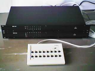
Crosspoint Router ARS-8x2 (audio unit of the AVRS-8x4 System)
|
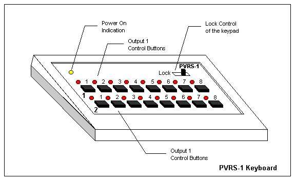
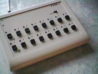
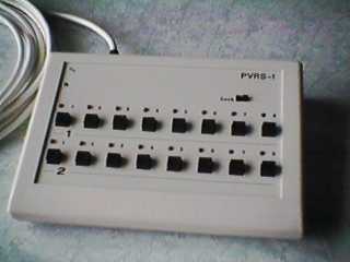
The AVRS-8x4 routing system incorporates two independent devices with a powerful control system – the VRS-8x4 video routing system with 8 inputs and 4 outputs and the ARS-8x2 stereo audio routing system with 8 stereo inputs and 2 stereo outputs. The device is easy to use due to a sophisticated microprocessor-based design that allows many powerful features such as the storage of a StartUp configuration and the switching on the vertical Sync Pulse. The system is controlled through the build-in RS232 control port by a PC, running a Windows-based Graphical User Interface Application (included). Control from the PVRS-1 keyboard is also possible. The keyboard should be connected to the serial MASTER-port of the first device in the stack with the power banana jack inserted. If connected to the VRS-8x4 system the keyboard provides switching of Output_1 and Output_2 only, Output_3 mirrors Output_1 and Output_4 mirrors Output_2. To view the main window of the Control Application of the AVRS-8x4 System click here.
The devices can be stacked to provide simultaneous control over more than 2 routers from a single computer. Every master device is connected to the next slave device through a serial connection (the slave output of the device is connected with a standard serial cable to the master input of the next device in the stack). To view different configurations for stacking VRS-8x4 and ARS-8x2 devices click here.
For broadcast “on-air” mode application or video editing purposes switching takes place during the vertical interval (according to the proposed SMPTE RP 165 Standard) by one of the input signals or by composite synchro-input. Composite synchro-output separated from the master video input signal is also available.
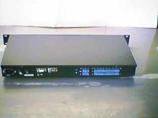
Video inputs are BNC 75 Ohm loaded connectors. The video
outputs are 75 Ohm wideband amplified, BNC connector type fitted.
Audio inputs are high impedance stereo type. Low impedance
drivers (600 Ohm) provide undistorted balanced audio outputs. Screw type
connectors are used for input and output connectors.
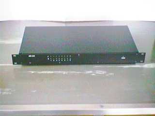
AVRS-8x4 is mounted in two compact 19” metal chassis in universal 1RU modular frame for rack mounting or for stand-alone application.
 |
 |
| Impedance (input) | > 20 kOhm balanced (600 Ohm optional) |
| Level (input) | +27 dBu maximum |
| Number of inputs | 8 balanced stereo |
| Common mode rejection (input) | >40 dB, 20Hz to 20kHz |
| Impedance (output) | 600 Ohm balanced |
| Level (output) | +27 dBu maximum |
| Number of outputs | 2 balanced stereo |
| Gain | 1 |
| Frequency response | <±0.25 dB, 20Hz to 20kHz |
| Total harmonic distortion | 0.03%, 20Hz to 20kHz |
| Intermodulation distortion | < 0.05 % (SMPTE) |
| Crosstalk | > 60 dB to 20 kHz |
| Noise Floor | -75 dBu, 30kHz BW |
| Coupling | DC |
| DC on output | ±50 mV maximum |
| Connectors | Screw type |
| Local control | PC control |
| 2 rows x 8 LED's | Type: GUI-application, running under Windows 95,98 |
| Configuration: Full control, stackable | |
| Interface: Serial RS-232, 9600 bps |
| Height | 44 mm (1RU, 1.75 inches) |
| Width | 483 mm (19.00 inches) |
|
|
235 mm (9.00 inches) |
| Weight | 1.7 Kg |
| Temperature | +5 deg.C to +35 deg.C |
| Humidity | 96% maximum |
| Power | 198-230 VAC, 50Hz, 8 VA |
|
PVRS-1 Keyboard
|
 |
 |
|
|